



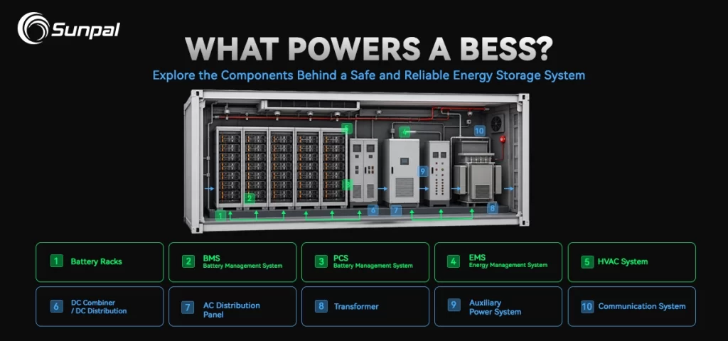
Battery energy storage has become the backbone of modern renewable power. As solar farms and hybrid projects scale worldwide, developers increasingly turn to containerized solutions that deliver reliable capacity, fast deployment, and robust safety. A BESS container—often called a containerized battery energy storage system—is far more than batteries stacked inside a metal box. It is a tightly engineered package that combines high-density lithium batteries, intelligent controls, thermal management, power conversion, and multi-layer safety systems inside a standardized shipping-container footprint.
Understanding what sits inside these units helps project developers, EPC contractors, asset owners, and solar companies make better decisions on performance, lifecycle cost, and long-term reliability. This article walks through the core components, typical internal layout, and critical safety systems that define today’s leading containerized energy storage solutions.
Why Containerized Battery Storage Matters for Solar Projects
Solar energy production peaks during the day, yet demand often continues into the evening. Pairing photovoltaic systems with energy storage solves this mismatch, enabling higher self-consumption, peak shaving, grid services, and backup power. Containerized BESS units have emerged as the preferred format for commercial, industrial, and utility-scale solar-plus-storage projects because they arrive factory-tested, travel as standard cargo, and install with minimal on-site civil works.
Modern 20-foot and 40-foot containers commonly deliver several megawatt-hours of usable capacity. Liquid-cooled designs now routinely pack 4–6 MWh or more into a single 20-foot high-cube enclosure—roughly double the density of systems from only a few years ago. This density, combined with modularity, makes containerized solutions ideal for hybrid solar plants, microgrids, and large-scale renewable energy storage applications.
Energy Density Progress in 20-Foot BESS Containers (2020–2026)
Typical mainstream capacity vs. leading-edge commercial examples
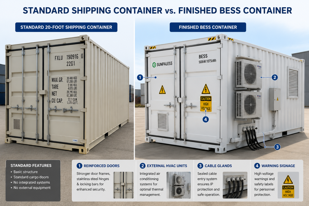
The Outer Shell: More Than Just a Shipping Container
At first glance a BESS container resembles a standard ISO shipping container. In reality the enclosure is purpose-built for decades of outdoor service. High-weather-resistant steel, advanced corrosion coatings, thermal insulation, and UV-resistant finishes protect internal equipment across desert heat, coastal humidity, and cold climates. Typical protection ratings reach IP54 or IP55, with some designs achieving higher seals around critical openings.
Structural engineering accounts for wind loads, seismic zones, and transport stresses. Doors provide both equipment access and emergency egress. Grounding points, filtered ventilation openings, and external connection panels complete a package designed for a 25-year service life. The container itself becomes the first layer of environmental and physical protection for the valuable systems inside.
Core Components: The Heart of a Containerized BESS
Every high-performance BESS container contains a coordinated set of subsystems. Understanding each one reveals why system quality varies so widely among suppliers.
Battery Cells, Modules, and Racks – Where Energy Lives
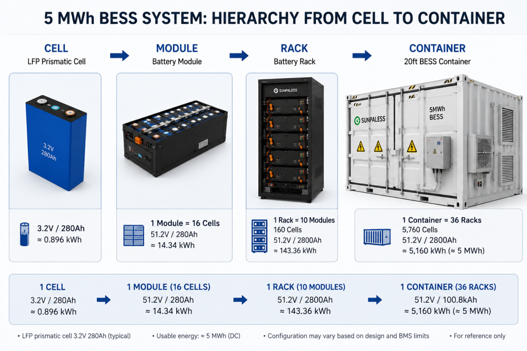
The energy storage core begins with individual lithium-ion cells, almost always lithium iron phosphate (LFP) for stationary applications. LFP chemistry offers superior thermal stability, long cycle life (commonly 6,000 to more than 10,000 cycles at recommended depths of discharge), and lower risk of thermal runaway compared with higher-energy-density chemistries.
Cells are grouped into modules or packs that include busbars, temperature sensors, and structural housing. Multiple modules stack into battery racks or clusters. A typical modern 20-foot liquid-cooled container may contain thousands of cells arranged in several parallel racks, delivering multi-megawatt-hour capacity. Racks include mechanical supports, electrical isolation, and interfaces for cooling and monitoring. This hierarchical design—cells to modules to racks—enables efficient manufacturing, testing, and future serviceability.
Battery Management System – The Intelligent Guardian
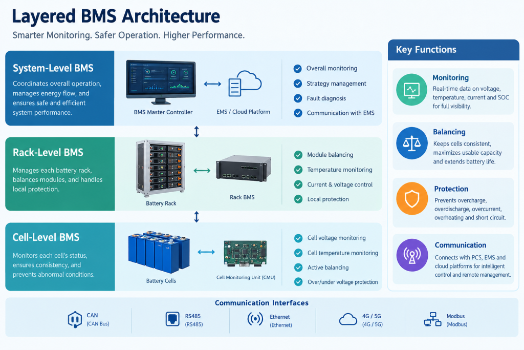
The BMS continuously monitors voltage, current, and temperature at cell, module, and rack levels. It performs active or passive balancing to keep cells within tight voltage windows, estimates state of charge and state of health, and enforces protective limits. If any parameter drifts outside safe bounds, the BMS can isolate the affected section or command a controlled shutdown.
Multi-tier architectures (cell-level boards, rack controllers, and system masters) communicate via CAN, Modbus, or Ethernet. High-quality BMS data also feeds predictive maintenance platforms, helping operators maximize the return on solar storage investments.
Power Conversion and Electrical Systems
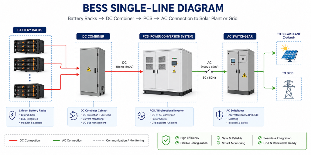
Batteries store energy as direct current. The power conversion system (PCS)—a bidirectional inverter—converts between DC and AC so the storage unit can charge from solar inverters or the grid and discharge to loads or the utility. Some designs integrate the PCS inside the container; others locate it in an adjacent outdoor cabinet.
Supporting electrical equipment includes DC combiners, high-voltage disconnects, fuses, surge protection, grounding systems, and auxiliary power supplies. Clean, well-engineered cabling and isolation are essential for both efficiency and safety in large solar-plus-storage installations.
Thermal Management – Keeping Performance Consistent
Battery performance and lifespan depend heavily on temperature control. Cells generate heat during charge and discharge; without effective management, temperatures can drift, accelerating degradation or creating safety risks.
Air-cooled systems using HVAC units remain suitable for lower-density or milder-climate applications. Higher-density containers increasingly adopt liquid cooling: cold plates mounted against modules circulate coolant that carries heat to an external or internal chiller. Liquid cooling delivers tighter temperature uniformity across the pack, supporting higher charge/discharge rates and longer life—key advantages for demanding solar energy storage duty cycles.
Air Cooling vs. Liquid Cooling in BESS
A side-by-side comparison of thermal performance, energy density, operating capability, and environmental adaptability for modern LFP-based battery energy storage systems.
When Air Cooling Makes Sense
A cost-effective choice for smaller BESS projects, lower power requirements, and installations located in relatively mild climates.
Why Liquid Cooling Is Becoming the Standard
Higher energy density, improved temperature consistency, and stronger climate adaptability make liquid cooling increasingly preferred for utility-scale and high-density C&I BESS applications.
Energy Management and Auxiliary Systems
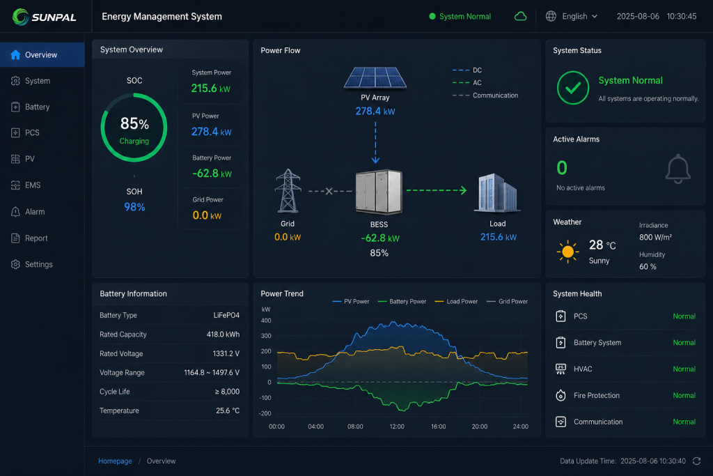
An energy management system (EMS) sits above the BMS and PCS. It optimizes charge and discharge strategies according to solar production forecasts, electricity tariffs, grid signals, or site load profiles. Local HMIs and remote SCADA interfaces give operators full visibility.
Auxiliary systems round out the package: internal lighting, environmental sensors, closed-circuit cameras, fire-system interfaces, and auxiliary power distribution keep the container functional and monitorable around the clock.
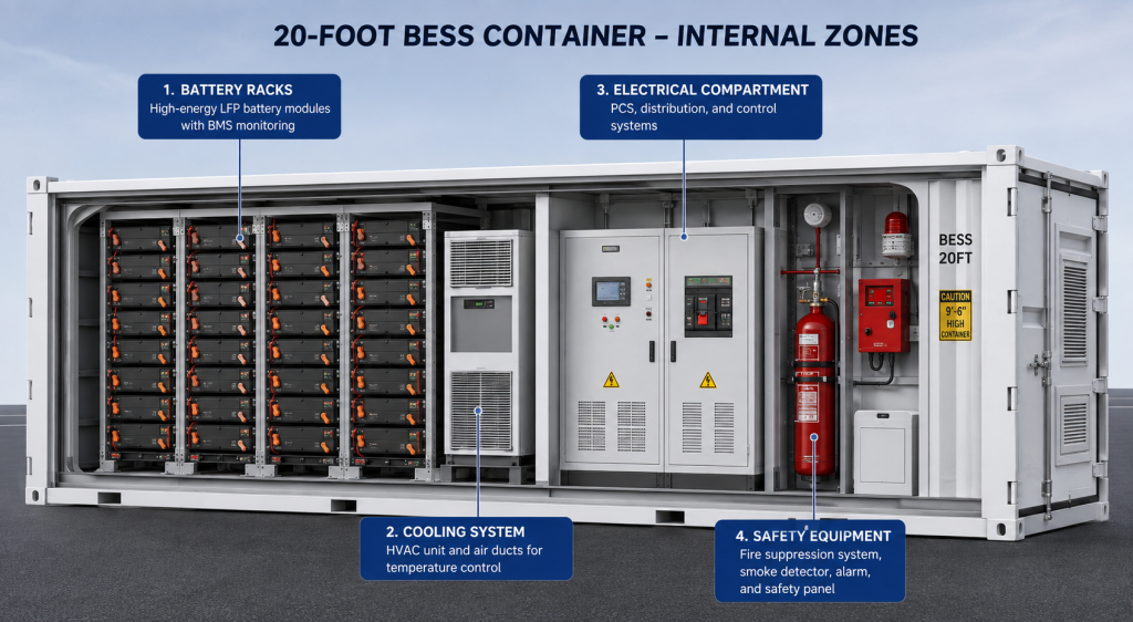
Inside the Box: How Everything Fits Together
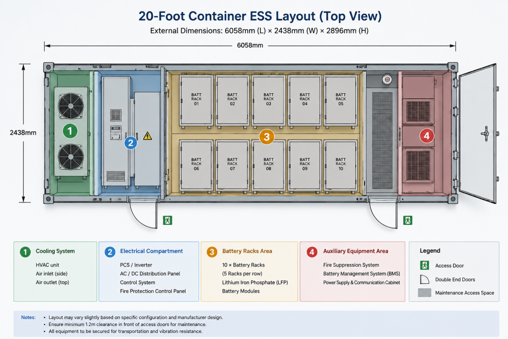
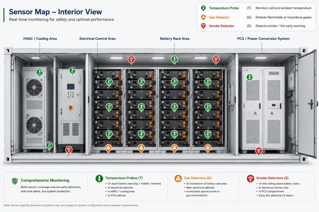
Layout design balances energy density against maintainability, thermal performance, and fire safety. A common approach divides the container into functional zones. Battery racks occupy the majority of the floor space, arranged in parallel rows with service aisles or front-access clearances. A fire-rated bulkhead often separates the battery compartment from an electrical or PCS section. Auxiliary equipment—chillers, fire-suppression cylinders, control cabinets—occupies remaining space, frequently near one end for easier external access.
Coolant piping, high-voltage DC busbars, and communication cables follow carefully planned routes that minimize electromagnetic interference and allow inspection. Cable penetrations through bulkheads use intumescent fire-stopping materials. Weight distribution and center of gravity receive attention so the unit remains stable during transport and lifting.
Well-designed layouts make routine inspections and component replacement straightforward while ensuring that a fault in one zone is less likely to cascade into another. These spatial decisions directly influence both operational uptime and safety outcomes for solar storage assets.
Multi-Layer Safety Systems: Protecting People, Assets, and the Grid
Safety remains the single most important design priority in any battery energy storage system. Modern containers employ layered defenses that begin at the cell level and extend to the entire installation.
Inherent Prevention
LFP chemistry, conservative operating windows enforced by the BMS, quality cell manufacturing, and effective thermal design form the first line of defense. Keeping cells within their recommended temperature and voltage ranges dramatically reduces the probability of thermal runaway.
Early Detection
Sensors monitor temperature at multiple points inside modules and racks. Smoke detectors and, increasingly, gas sensors that detect hydrogen, carbon monoxide, or electrolyte off-gassing provide early warning of abnormal conditions—often before visible smoke appears. These signals feed both the local BMS and external fire-alarm panels.
Electrical Isolation
Fast-acting disconnects, fuses, and ground-fault detection can isolate a problematic rack or string within milliseconds. Emergency power-off circuits allow rapid de-energization from outside the container.
Suppression and Mitigation
If a thermal event progresses, automatic suppression systems activate. Clean-agent gases, condensed aerosols, or water-mist systems are commonly used. Many designs now combine pack- or rack-level detection and suppression with container-level total flooding for additional protection. Pressure-relief vents and controlled ventilation pathways manage gas release and overpressure.
Compartmentalization limits the spread of heat or fire between battery zones and critical control equipment. Structural materials and fire-rated barriers further contain events so that neighboring containers or adjacent solar equipment remain protected.
Five Layers of Battery Safety
A coordinated protection architecture that progressively prevents, detects, isolates, suppresses, and contains thermal events throughout a modern containerized BESS.
Prevention
Stop the event before it startsInherent design and operational controls reduce the probability of abnormal thermal conditions developing.
Detection
Identify abnormal conditions earlyContinuous monitoring identifies abnormal temperature, smoke, gas, and electrical conditions before escalation.
Isolation
Interrupt the energy pathFast electrical separation stops energy flow into the affected rack, string, or battery section.
Suppression
Control an active thermal eventActive extinguishing and cooling systems respond to thermal events and reduce heat or fire intensity.
Containment
Limit propagation beyond the affected areaPhysical barriers and structural features help limit thermal propagation to adjacent equipment and units.
Standards, Testing, and Operational Safeguards
Leading systems are evaluated to UL 9540 and undergo UL 9540A thermal-runaway testing at cell, module, and unit levels. Installation practices follow NFPA 855 guidance on separation distances, ventilation, and hazard mitigation. Regular monitoring, firmware updates, and trained response procedures complete the safety ecosystem.
These multi-layer approaches have significantly improved the safety profile of containerized energy storage, giving solar developers and financiers greater confidence in large-scale deployments.
Key BESS Safety Standards
| Standard | Primary Focus | One-Sentence Description |
|---|---|---|
|
01
UL 9540
|
System Safety | System-level safety standard that evaluates the construction, performance, and integration of complete energy storage systems, including electrical, mechanical, and environmental aspects, for listing and code compliance. |
|
02
UL 9540A
|
Thermal Runaway Test | Test method that evaluates thermal runaway fire propagation at the cell, module, unit, and installation levels to characterize fire, gas, and explosion hazards. |
|
03
NFPA 855
|
Installation Safety | Installation standard specifying requirements for safe siting, separation distances, fire protection, ventilation, and operation of stationary energy storage systems. |
|
04
IEC 62933-5-2
|
Electrochemical ESS | International safety standard providing requirements for grid-integrated electrochemical energy storage systems, covering design, operation, and protection throughout the system lifecycle. |
|
05
IEC 62619
|
Battery Safety | Safety requirements standard for secondary lithium cells and batteries used in industrial applications, including stationary energy storage, covering overcharge, short-circuit, thermal, and propagation risks. |
|
06
IEC 62933-5-1
|
General ESS Safety | General safety considerations standard for grid-integrated electrical energy storage systems across technologies, serving as the foundation for more specific electrochemical requirements. |
Practical Benefits and What the Future Holds
Containerized BESS units accelerate project timelines. Factory acceptance testing reduces on-site risk, modular capacity allows phased expansion, and standardized logistics simplify global deployment. For solar companies and independent power producers, the result is faster revenue generation and more predictable performance.
Looking ahead, energy densities continue to rise with larger-format cells and refined packing. Liquid cooling is becoming standard for high-performance applications. Smarter multi-level BMS and EMS platforms incorporate advanced diagnostics and even AI-assisted optimization. Detection technologies grow more sensitive, and suppression strategies become more targeted. Integration with solar forecasting, virtual power plants, and grid-forming inverters will further increase the value of these systems.
Projected BESS Energy Density & Cycle Life Through 2030
| Year | Typical Energy Density 20-ft Container |
Leading-Edge Energy Density | Typical Cycle Life | Key Drivers |
|---|---|---|---|---|
|
2026
|
5.5 – 6.5
MWh / container
|
6.5 – 8.0+
MWh / container
|
8,000 – 12,000
CYCLES
|
Current mainstream with 314–587 Ah LFP cells; liquid cooling increasingly standard. |
|
2027
|
6.0 – 7.0
MWh / container
|
7.0 – 9.0
MWh / container
|
10,000 – 13,000
CYCLES
|
Wider adoption of 587–700+ Ah cells and improved internal packing efficiency. |
|
2028
|
6.5 – 7.5
MWh / container
|
7.5 – 10.0
MWh / container
|
11,000 – 14,000
CYCLES
|
Further cell capacity gains combined with system-level optimization. |
|
2029
|
7.0 – 8.0
MWh / container
|
8.0 – 11.0
MWh / container
|
12,000 – 15,000
CYCLES
|
Advanced electrode compaction and increasingly optimized thermal management. |
|
2030
|
7.5 – 9.0
MWh / container
|
9.0 – 12.0+
MWh / container
|
12,000 – 15,000+
CYCLES
|
Next-generation large-format LFP and refined system designs; logistics remain a practical limit. |
Choosing and Operating Containerized Storage Wisely
When evaluating solutions, focus on verified cycle life data, thermal management method, suppression architecture, third-party certifications, and service accessibility. Ask for UL 9540A test summaries and clear descriptions of how the system behaves under fault conditions. Once installed, consistent remote monitoring and scheduled inspections protect the investment over its multi-decade life.
A well-designed BESS container transforms intermittent solar generation into dispatchable, reliable power. By combining high-quality batteries, intelligent controls, effective thermal management, and rigorous safety engineering inside a rugged enclosure, these systems deliver the performance modern renewable projects demand.
As solar capacity continues its global expansion, understanding the technology inside the container becomes essential knowledge for everyone involved in building the clean energy systems of tomorrow.
Ready to Power Your Next Solar Project with Containerized BESS?
Whether you are planning a new hybrid solar plant, upgrading an existing commercial solar installation, or exploring large-scale renewable energy storage options, the right containerized BESS can unlock greater energy independence, higher returns, and long-term grid resilience. Explore Sunpal's range of proven solar-plus-storage solutions, review detailed technical specifications, or speak with our engineering team to discover how a tailored BESS container can power your next project with confidence and efficiency.